Separating Air.
Powering Industry.

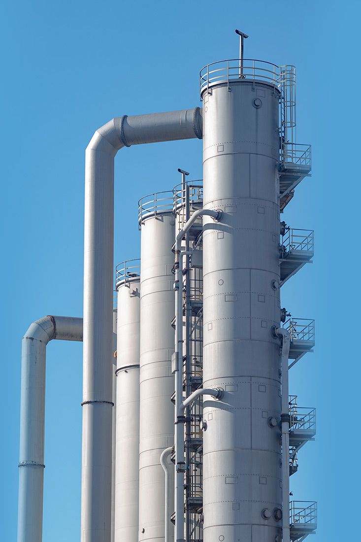
Our Air Separation Units (ASUs) are designed in-house and produce oxygen, nitrogen, and argon for a wide range of product flows, pressures and purities common across multiple industries.

Oxygen, Nitrogen, Argon – At Scale.
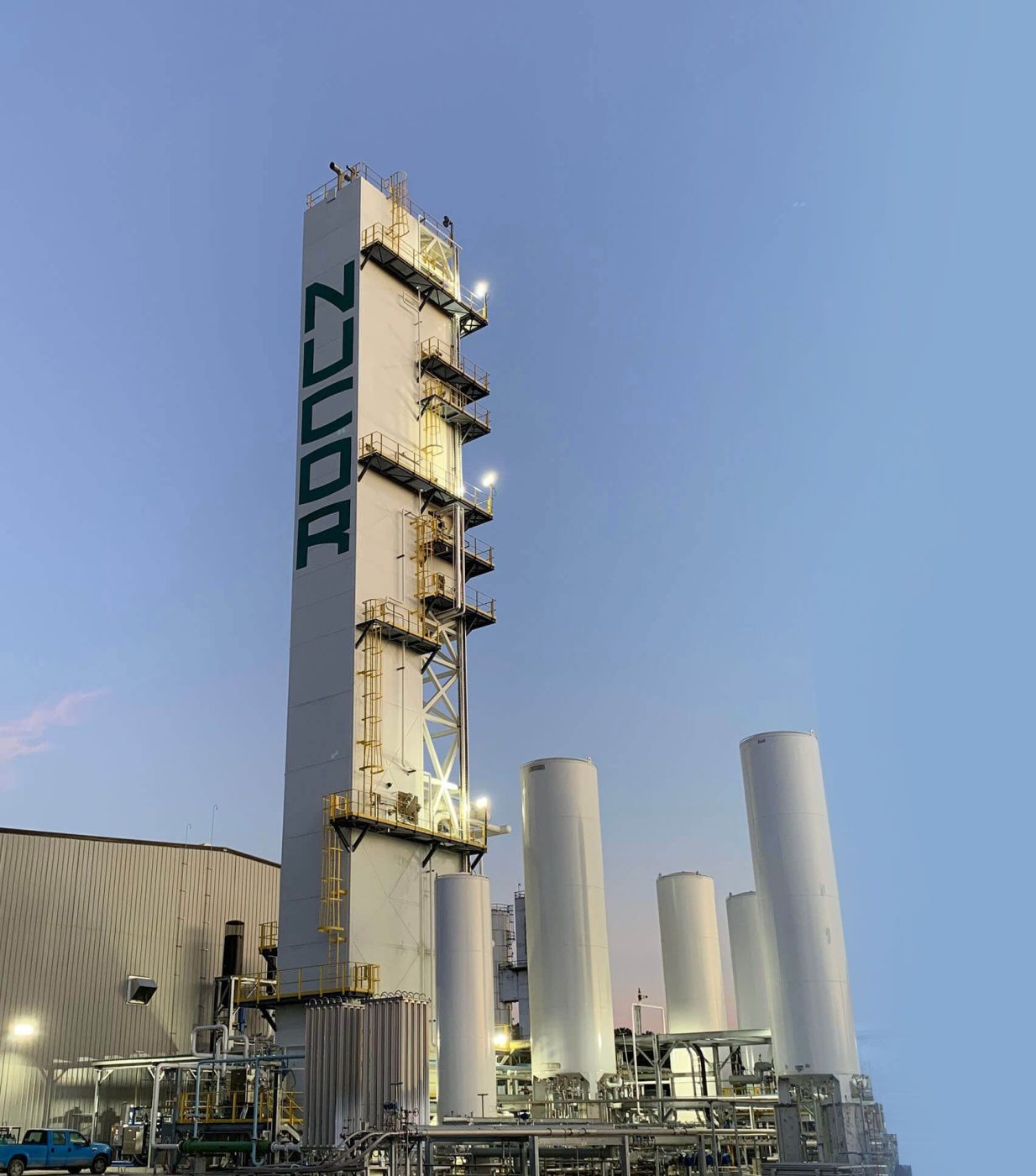
UIG personnel have experience delivering ASU’s for under 100 tons of product per day to over 2,000, serving customers with demands small and large alike.

Energy Efficient
The largest cost for ASU operation is electricity! UIG leverages modern advancements in distillation, machine efficiency, insulation, and more to build plants with lower specific power.

Reliable Supply
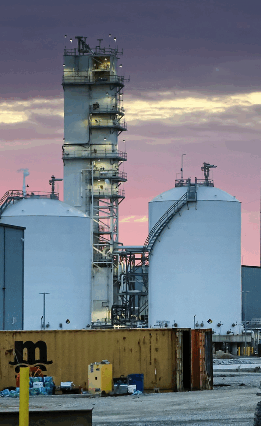
UIG designs its ASUs with operations and maintenance in mind. Our flowsheets and physical layouts are carefully planned to reduce single points of failure and keep critical maintenance envelopes available.

Nitrogen Plants, Too
In addition to our multiproduct ASUs, UIG designs and builds simpler cryogenic plants that strictly produce nitrogen. A great answer for large nitrogen applications, UIG cryogenic nitrogen plants are built with the same principles as our ASUs.
Turn Air Into Essential Gases
Our cryogenic air separation plants deliver high-purity oxygen, nitrogen, argon and rare gases with unmatched reliability, and are ideal for industries that demand precision, efficiency, and continuous supply.

Oxygen Production
Supports clean combustion, oxidation, and life-support melting.

Nitrogen Production
An inert gas used for cooling, blanketing, and pressurization.

Argon Production
A noble gas ideal for shielding and specialized applications.
ASUs Purpose-Built for
Your Industry
From steel and chemicals to energy and glass, our cryogenic storage systems are tailored to meet the unique gas demands of your industry.

Steel

Our ASUs deliver high-purity oxygen and nitrogen, engineered for seamless integration into steel production.

Energy
We design ASUs that support gasification, LNG, and power generation with reliable gas supply.

Glass
Our air separation plants optimize oxygen supply for glass manufacturing, improving efficiency and quality.

Chemicals
Custom-built ASUs provide the industrial gases essential for efficient chemical processing and production.

Mining and Minerals
We build ASUs to support metal extraction and mineral processing with consistent oxygen delivery.

Metals
From refining to heat treatment, our ASUs provide the gases needed for high-performance metal production.
Gas Supply, Your Way
UIG gives you the freedom to choose how you source your gas – whether you want a fully managed solution or complete control over your production. Our flexible approach ensures you get the reliability, efficiency, and cost structure that works best for you.
Cryogenic Air Separation FAQs
What is cryogenic air separation?
Cryogenic air separation is a process that cools air to extremely low temperatures to liquefy its components, allowing for the separation of oxygen, nitrogen, argon, and rare gases through distillation.
How does cryogenic air separation work?
The process involves compressing and purifying air, cooling it to a liquid state, separating its components by distillation, and then delivering purified gases for industrial use.
What gases can be produced through cryogenic air separation?
The primary gases produced are oxygen, nitrogen, and argon, along with rare gases such as neon, krypton, and xenon.
What industries rely on cryogenic air separation plants?
Industries such as steel, energy, glass, chemicals, mining, and metals depend on cryogenic air separation for a steady and high-purity gas supply.
What are the advantages of cryogenic air separation over other gas production methods?
Cryogenic separation has advantages over non-cryogenic counterparts by way of product diversity, product purity, product storage, and scale. An ASU can produce purified oxygen, nitrogen, and argon making it the ideal choice for operations consuming multiple gas products. ASUs are also capable of achieving higher oxygen and nitrogen purities than non-cryogenic plants. ASUs can make liquid products for backup storage and supply while non-cryogenic plants only produce gaseous products that aren’t available when the plant isn’t running. Finally, for large use applications the economics of ASUs scale up far better than non-cryogenic assets.
Why does ambient air need to be compressed and purified?
Ambient air contains moisture, carbon dioxide, and other impurities that can freeze or interfere with the cooling and separation process. Compression increases air density, while purification removes these contaminants to ensure safe and efficient gas production.
How is air turned into a liquid?
After purification, the air is cooled to cryogenic temperatures—often below -300°F—causing it to condense into a liquid. This step is essential to prepare the air for separation, since different gases liquefy at different temperatures
How are different gases separated from liquefied air?
Using advanced distillation columns, the liquefied air is separated into nitrogen, oxygen, and argon. Each gas has a distinct boiling point, allowing them to be isolated through careful temperature control.
What happens after the gases are separated?
The gases undergo a final purification step to meet industry or customer-specific purity standards. They are then stored in liquid or gaseous form and delivered directly through pipelines or used onsite.
How do I determine the right air separation solution for my business?
The best solution depends on your volume requirements, operational preferences, and financial strategy. UIG works with you to develop a tailored gas supply plan.
What makes UIG different from other industrial gas suppliers?
UIG offers flexible supply options, from turnkey plants to DIY solutions, ensuring that you get a gas supply model that aligns with your business needs – not the supplier’s bottom line.
Where does UIG operate?
UIG, a wholly owned subsidiary of Nucor Corporation, designs, builds, and operates air separation plants across North America.
What services does UIG provide beyond air separation plants?
We offer plant design, construction, operation, maintenance, and consulting services to ensure your industrial gas supply is efficient and cost-effective.
How can I get started with UIG?
Contact us to discuss your gas supply needs, and our team will help you determine the best solution for your business.
Cryogenic Air Separation Resources
Resource 1
An inert gas used for cooling, blanketing, and pressurization.
Resource 2
An inert gas used for cooling, blanketing, and pressurization.
Resource 3
An inert gas used for cooling, blanketing, and pressurization.
Gas You Can Work With
Discover a better way to work with industrial gas with UIG. Get in touch today to learn more.